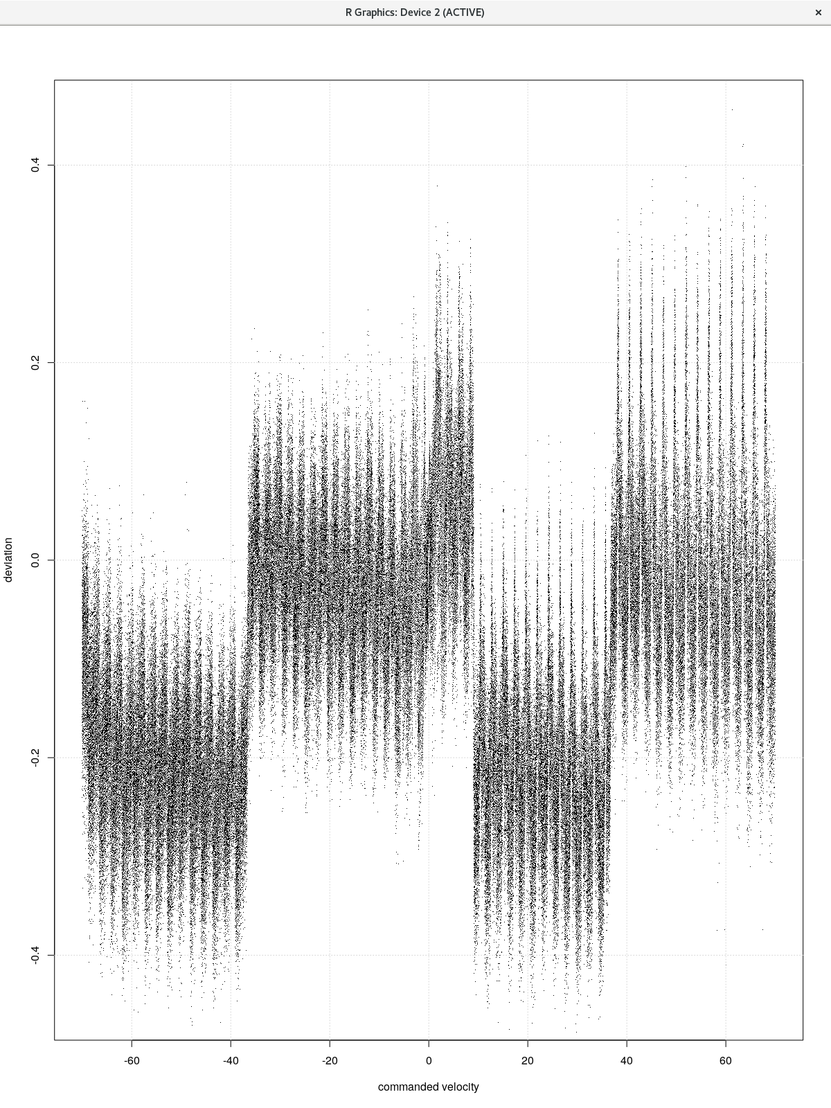
I’m fairly satisfied with my servo tuning results. Pretty much within a 10 micron bound at the path reversals with acceleration set to 800mm/s2 and velocity at 300mm/min.
The deviation from the planned path is within a couple of microns during the constant velocity sections of the motion. I think I can reduce that further by compensating for the error measurements I’ve made of the analog drive system.
An analog +/- 10V signal commands the velocity of the servo drive. That signal is derived from a filtered PWM source. Sweeping the signal range while measuring the servo velocity gives a scatter graph like this:
Applying the mean to a sliding bin of size 0.1mm/s shows that both axes have very similar responses once the gain has been nulled.
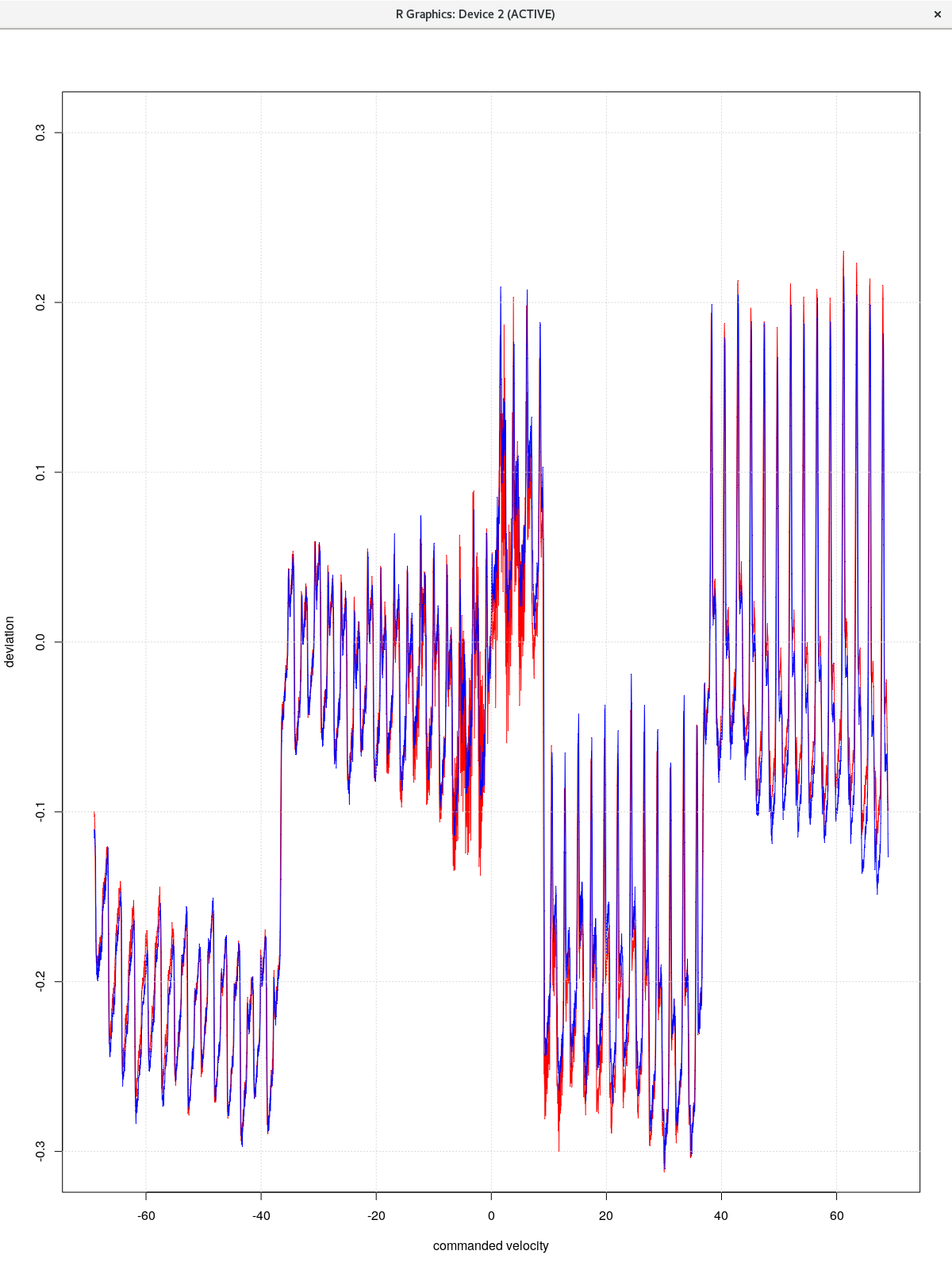
Overall the velocity of the servos are within 0.3mm/s of the commanded speed over a range of +/- 67mm/s. (2000rpm @ 2mm/rev). While very good, this error feeds into the PID loop, and is quite characterizable, so there is room for improvement.
Here a short video of the test system running. The first portion shows the high speed performance while following the ‘EMC AXIS’ path. The second portion shows holding a tolerance of better than 20 microns over a simple path programmed at 300mm/min.
The first part of that video should probably have been in slow motion.
What controller are you using for this setup?
These are CTB servos and drives. The interface is an Ethernet connected Mesa FPGA card.